-
Read the WELCOME ALL BMWFANATICS post.
You are using an out of date browser. It may not display this or other websites correctly.
You should upgrade or use an alternative browser.
You should upgrade or use an alternative browser.
M40b18
- Thread starter Pokie
- Start date

Nastaliq
Well-known member
if I am not mistaken thats a 55 pin connector then.
TIS says:
Ignition and Control:
TIS says:
Ignition and Control:
- Pin 25 – Cylinder 1 Ignition Coil
- Pin 24 – Cylinder 3 Ignition Coil
- Pin 52 – Cylinder 2 Ignition Coil
- Pin 51 – Cylinder 4 Ignition Coil
- Pin 55 – Ignition Ground
- Pin 56 – Ignition Switch Input
- Pin 3 – Injectors 2 and 4
- Pin 32 – Injectors 1 and 3
- Pin 6 – Injector Ground
- Pin 67 – Crank Position Sensor Input
- Pin 68 – Crank Position Sensor Output
- Pin 70 – O2 Sensor Input
- Pin 71 – O2 Sensor Ground
- Pin 78 – Coolant Temperature Input
- Pin 59 – TPS and VAF 5V Reference
- Pin 12 – TPS Input
- Pin 41, 76, 77 – Volume Air Flow Sensor Inputs
- Pin 15, 42 – Knock Sensor Inputs
- Pin 43 – Ground for Temp, Knock, and Throttle Sensors
- Pin 60 – Data Link Connector Input
- Pin 87 – Data Link Connector RxD
- Pin 88 – Data Link Connector TxD
- Pin 8 – Check Engine Light
- Pin 26 – Battery Voltage Input
- Pin 27 – Engine Control Relay Output
- Pin 28, 34 – Ground
Attachments
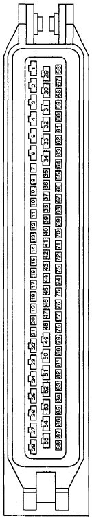

Heres your plug connector pinout.
If i am correct pin 25 goes to the coilHeres your plug connector pinout.
And a few new questions...
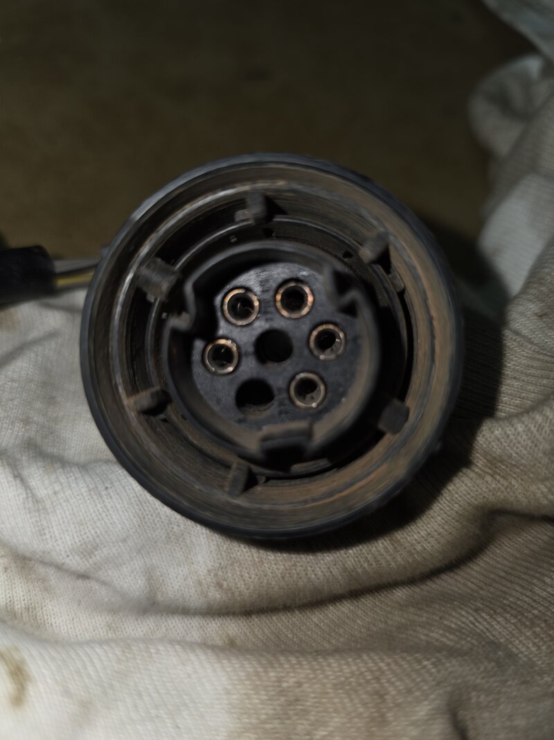
1. Is Pin 6 going to ground? ...the. injectors have 3 wires. ...pin 1 red and white (12v+) pin 2 brown and white(inje 1and 3) pin 3 brown and yellow( ing 2 and 4) is the injectors getting permanent 12v+and a negative signal form dme to activate
2. Where must pin 55 go. (Ignition ground)
3. I have a wire on pin 16 and 44. I think it ia cylinder id sensor........what is that and where must it go? It have a plug on the end same as the cps plug.
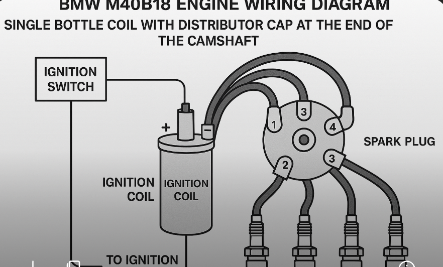
4. Is the Coil is getting 12v+from ignition and 12v negative signal from pin 25 on the dme?
5. I am left with 1 wire on the plug as in the above pic what i did not know where it is going.....turns out it is the air flow meter. It is a grey wire with a white stripe. Perhaps a ground? The other 4 wires goes to the dme.
Thanks a lot for all the help.
1. Is Pin 6 going to ground? ...the. injectors have 3 wires. ...pin 1 red and white (12v+) pin 2 brown and white(inje 1and 3) pin 3 brown and yellow( ing 2 and 4) is the injectors getting permanent 12v+and a negative signal form dme to activate
2. Where must pin 55 go. (Ignition ground)
3. I have a wire on pin 16 and 44. I think it ia cylinder id sensor........what is that and where must it go? It have a plug on the end same as the cps plug.
4. Is the Coil is getting 12v+from ignition and 12v negative signal from pin 25 on the dme?
5. I am left with 1 wire on the plug as in the above pic what i did not know where it is going.....turns out it is the air flow meter. It is a grey wire with a white stripe. Perhaps a ground? The other 4 wires goes to the dme.
Thanks a lot for all the help.
Nastaliq
Well-known member
howsit
Pin 1 (Red/White): Yes, this is normally 12V+ from ignition. All injectors receive constant 12V+ here. Pin 2 (Brown/White): Controls injectors 1 and 3. This is the negative trigger from the DME. Pin 3 (Brown/Yellow) controls injectors 2 and 4, also a negative trigger from the DME.
2.Pin 55 should be connected to a clean chassis ground or engine ground. It ensures proper grounding for ignition-related components. Do yourself a favour and make sure this grounding is properly done with the right gauge cable and secure it mechanically, dont take a shortcut since improper grounding will create lots of other issues and ghost faults for nothing if you dont make sure. Make sure.
3. These pins are for the Cyl-ID sensor, which helps the DME identify cylinder #1 for and ignition timing.usually it mounts near the camshaft or flywheel, and yes, it uses the same cps plug type.Connect it to the sensor input on the DME and ground it properly. Make sure, then make sure again.
4. The ignition coil gets 12V from ignition switch via a relay. Negative trigger from Pin 25 on the DME to fire the coil.
5. that one wire left which is grey with white strip is ground or signal ground for the airflow meter. The other 4 wires that go to the DME are 12V+, Ground, Signal output to DME and the Air temp sensor signal.
check all this properly with a wiring diagram. I am not a pro at this. I dont do any of this stuff anymore. Ive been electrocuted many times from bad choices and not using adequate lighting to check wiring colours properly. Red, brown and pink all look the same to me on old wiring sheaths.
I need glasses.
Hi. Thanks for all the help. Got it started . One more question. Does this ecu have a limp mode. Car is revving to abour 2000 rpm and loses spark. I tested with a led testlight on the coil signal(negative) and i have consistent spark to 2000rpm but after that i can see it looks like it fires less times per revolution...howsit
Pin 1 (Red/White): Yes, this is normally 12V+ from ignition. All injectors receive constant 12V+ here. Pin 2 (Brown/White): Controls injectors 1 and 3. This is the negative trigger from the DME. Pin 3 (Brown/Yellow) controls injectors 2 and 4, also a negative trigger from the DME.
2.Pin 55 should be connected to a clean chassis ground or engine ground. It ensures proper grounding for ignition-related components. Do yourself a favour and make sure this grounding is properly done with the right gauge cable and secure it mechanically, dont take a shortcut since improper grounding will create lots of other issues and ghost faults for nothing if you dont make sure. Make sure.
3. These pins are for the Cyl-ID sensor, which helps the DME identify cylinder #1 for and ignition timing.usually it mounts near the camshaft or flywheel, and yes, it uses the same cps plug type.Connect it to the sensor input on the DME and ground it properly. Make sure, then make sure again.
4. The ignition coil gets 12V from ignition switch via a relay. Negative trigger from Pin 25 on the DME to fire the coil.
5. that one wire left which is grey with white strip is ground or signal ground for the airflow meter. The other 4 wires that go to the DME are 12V+, Ground, Signal output to DME and the Air temp sensor signal.
check all this properly with a wiring diagram. I am not a pro at this. I dont do any of this stuff anymore. Ive been electrocuted many times from bad choices and not using adequate lighting to check wiring colours properly. Red, brown and pink all look the same to me on old wiring sheaths.
I need glasses.
Nastaliq
Well-known member
yes, it does have a basic limp mode.
but causes could be many. Could be coolant temp sensor, throttle position sensor, low voltage or ground faults (very common cause), MAF sensor reading incorrectly air volume, crank position sensor or other wiring issues which look like a sensor failure (redong out of parameter), so the ECU cuts off.
you problem sounds most like a crank sensor or coil driver. but i would also scan for codes and check crank sensor at idle with multimeter and then see what reading youre getting at 2000 revs. Check the coil negative as well, if the frequency or amplitude drop it can be the ECU or crank signal.
Finally clean and test the TPS and MAF sensors
Obviously as i said before check all grounds and power supply at higher load RPMs.
Youre officially at the stage where you may need a wiring specialist/electrical specialist with oscilloscope to help you.
Similar threads
- Replies
- 9
- Views
- 1K
- Replies
- 11
- Views
- 2K
- Replies
- 4
- Views
- 881